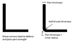
Design Guide Line
1. Ribs height and thickness
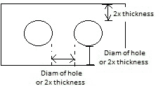
1-1. Heigh of Boss, H = 2.5D
Boss diameter, wall thickness, and height design parameters. While boss heights vary by design, the following guidelines will help avoid surface imperfections like sink marks and voids: the height of the boss should be no more than 2 1/2 times the diameter of the hole in the boss.

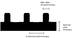
1-2. Rib-to-wall thickness ratios, 60%

1-3. Typical wall thickness
Wall thik. |
max[in] |
min[mm] |
max[mm] |
|
ABS |
0.045 |
0.140 |
1.143 |
3.556 |
PC |
0.040 |
0.150 |
1.016 |
3.810 |
PP |
0.025 |
0.150 |
0.635 |
3.810 |
PE |
0.030 |
0.200 |
0.762 |
5.080 |
PU |
0.080 |
0.750 |
2.032 |
19.050 |
* Fiber reinforced plastic allows for larger thicker parts
2. Minimizes Warpage
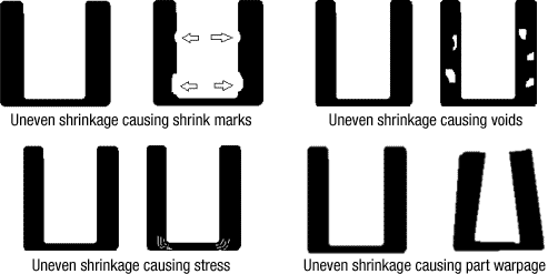
Warpage due to stresses in step transitions between wall thicknesses can be improved through the use of a ramp. The use of gussets can also provide support in corners to help avoid warping.A. High stress concentrations
B. Reduced stress concentrations
C. Thinner walls result in shrinkage during cooling
D. Gussets provide additional support to reduce warpage

3. Avoiding sink
Thicker and non-uniform wall thicknesses can often result in sinks in the material due to the same solidification physics described above. The use of thinner, uniform wall thicknesses helps to avoid sink.A. Boss in corner causes sink
B. Thinner walls on boss eliminates sink
C. Thick walls cause sink, warp & excess shrink
D. Thinner walls give accurate part

BURN MARKS

Burn marks can be defined as small dark brown or black discolorations on the surface of a molded part, usually found at the end of the material flow path or in blind pockets.
Machine
Excessive Injection Speed or Pressure
Explanation: Injection speed and pressure determine how fast molten resin is injected into a mold. If either is too high, the resin is forced in so fast that trapped air and gases are not allowed time to be vented. Many of these gases are pushed to the edge of the flow front and become compressed to the point that they auto-ignite, burning the surrounding plastic. The burned areas appear as char marks on the molded part.
Solution: Reducing the injection speed or pressure will allow enough time for the gases or trapped air to escape through normal vent paths.
Excessive Back Pressure
Explanation: While most materials will benefit from some back pressure application, there is a limit to the amount needed for a specific material and product. The whole idea of applying back pressure is to mix the material better, making it denser and more oriented for flow. However, this very act of mixing may introduce air into the melt, which may be too much for the venting system to handle under normal conditions. The excess air may be compressed at the vent locations and auto-ignite, causing burn marks on the part. There is also the possibility that shearing action from too high a back pressure setting will degrade the material in the barrel and cause burning to occur.
Solution: Use minimum back pressure. All materials will benefit from approximately 50-psi back pressure, but some require up to 300 psi. The material supplier is the best source of information regarding proper back pressure settings for a specific material. When adjusting back pressure use increments of 10 psi.
High Screw Rotation Speed
Explanation: The turning of the screw brings fresh material into the heating cylinder and imparts a certain amount of heat to that material through rotary shear friction. The faster the screw turns, the greater the friction and shear heat created. If the speed is too high, the friction will cause the material to overheat and become thermally degraded. This causes small particles of charred material to form and these get pushed into the melt stream during injection. They will show up on the molded part as burned areas.
Solution: Adjust the screw rotation speed. An average speed should be approximately 100 rpm. But, specific materials require specific rotation speeds. Consult the material supplier for the proper speed for a specific resin. When adjusting up or down, do so in increments of 10 rpm.
Improper Compression Ratio of Screw
Explanation: Compression ratio is a value that indicates how much a screw will compress a material while it is being processed in the barrel of the machine. It is calculated by dividing the depth of the feed section (rear) of the screw by the depth of the metering section (front) and is usually less than 2 to 1. If the compression ratio is too great for the specific material being molded, the resin degrades thermally and the burned material flows into the molded part.
Solution: The material supplier can recommend the proper compression ratio for a specific resin. A general-purpose screw can usually be used to provide adequate compression but specific conditions may require a screw that is specially designed for a given material.
Faulty Temperature Controllers and Heater Bands
Explanation: Temperature controllers are sensitive units and should be checked and calibrated often (every 3 months maximum). Heater bands do wear out or burn out and normally there is no way of knowing. If controllers or heater bands are not functioning properly, the other controllers and heater bands must compensate. The result is localized overheating of material in the cylinder. This material can degrade and char and enter the melt stream to become molded into the plastic part.
Solution: Inspect and calibrate temperature controllers at least every 3 months. Inspect and replace damaged heater bands as necessary. In addition, look for broken or crimped wires, poor insulation, rusted areas on the heater bands, and poor electrical connections.
Excessive Barrel Temperatures
Explanation: When barrel temperatures are set too high, the resin will overheat and undergo thermal degradation. This degraded material will break loose, enter the melt stream, and become molded into the finished part.
Solution: Establish proper barrel temperatures and profile. The material supplier will provide accurate barrel temperature requirements. The profile should have the barrel temperatures increase progressively from rear to front.
MOLD
Improper Sprue Bushing-To-Nozzle Sizing
Explanation: If the sprue bushing diameter does not match the nozzle opening (or vice-versa) molecular shearing will occur at their junction and some of the material flowing through that area will degrade. The degraded material will enter the melt stream and be molded into the finished part.
Solution: Using bluing dye or thick paper, press the nozzle against the sprue bushing, and check the impression of the openings of each. They should be close to the same and not be off center. Replace the nozzle tip or the sprue bushing if they do not match. Re-center the heating cylinder to the mold if they are off center.
Improper Venting
Explanation: Air is trapped in a closed mold and incoming molten plastic will compress this air until it auto-ignites. This burns the surrounding plastic and results in charred material in the form of burn marks.
Solution: Vent the mold by grinding thin (0.0005''-0.002'') pathways on the shutoff area of the cavity blocks. Vents should take up approximately 30% of the perimeter of the molded part. Vent the runner, too. Any air that is trapped in the runner will be pushed into the part. Blind pockets can be vented using flush core pins or fake ejector pins and grinding a flat down the entire length of the pins.
Undersized Gates
Explanation: Gates are used to determine the flow of the material into the cavity. They are intended to cause a slight restriction and impart shearing heat to the plastic, as well as to control the speed at which the plastic enters. If the gate is too small, the restriction is too great and the material will overheat causing degradation. The degraded material shows up as burned resin in the finished part.
Solution: Size the gate according to the material supplier's recommendations. The gate should be as thin as possible to minimize cycle time, but as thick as necessary to reduce the tendency to degrade material. Gates should be installed in removable inserts so they can easily be altered or replaced.
MATERIAL
Excessive Use of Regrind
Explanation: Regrind melts at a lower temperature than virgin, and a regrind/virgin blend must be heated high enough to melt the virgin, which may degrade the regrind. For this reason, regrind use should be minimized if mixed with virgin material. However, regrind by itself can be used successfully by lowering the melt temperature.
Solution: Use 100% regrind, or, if mixing with virgin, limit the amount of regrind to 15% by weight. It may be necessary to use no regrind at all, especially in some medical and electronic products.
OPERATOR
Inconsistent Process Cycle
Explanation: It is possible that the machine operator is the cause of delayed or inconsistent cycles. This will result in excessive residence time and erratic heating of the material in the injection barrel. If such a condition exists, materials may degrade, resulting in locally burned resin.
Solution: If possible, run the machine on automatic cycle, using the operator only to interrupt the cycle if an emergency occurs. Use a robot if an ``operator'' is really necessary. And, instruct all employees on the importance of maintaining consistent cycles.
5. Plastic Design Guideline
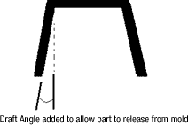
Undercut helps pull the part
A third approach is shown in Figure 6. Here the part is formed between a cavity in the A-side mold half and a core in the B-side. After cooling, the mold opens, leaving the part on the core. With nothing pressing against the outside of the part, the part wall is free to stretch as it is ejected off the B-side core, releasing the part with the inside ring intact.
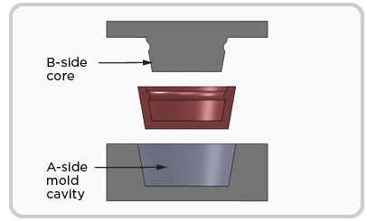
Figure 6 – Mold can be made core-cavity, allowing room for the part to “bump-off” after the mold opens
'Technology > Tech' 카테고리의 다른 글
| Getting started with airplane engineering (0) | 2016.03.08 |
|---|---|
| RF shielding enclosures design (0) | 2016.02.18 |
| Solar Power (0) | 2012.02.01 |
| Photovoltaic Glass Stands Up to 'Wall of Wind' (0) | 2012.01.17 |
| Corning Cable Systems Outdoor Cable Jacket Material – Medium Density Polyethylene (0) | 2011.12.25 |
